A transformer is a device that can increase (step-up) or decrease (step-down) voltage. In a step-up transformer, the output voltage is higher, but the output current is lower to maintain equal power input and output. Conversely, a step-down transformer decreases the output voltage while increasing the output current.
Transformers are essential for controlling voltage in the distribution and transmission of alternating current (AC) power. First discussed by Michael Faraday in 1831, transformers help balance the generation of electricity at high voltages with consumption at lower voltages.
What Is a Transformer?
A transformer is used to transmit electric energy, specifically AC. It changes the supply voltage without altering the frequency, working on principles of electromagnetic induction and mutual induction.
Types of Transformers
Transformers are classified based on:
- Voltage Levels:
- Step-up Transformer: Increases output voltage.
- Step-down Transformer: Decreases output voltage.
- Core Medium:
- Air Core Transformer: Uses air as the medium for flux linkage.
- Iron Core Transformer: Uses stacked iron plates to link flux.
- Winding Arrangement:
- Autotransformer: Has a single winding that acts as both primary and secondary.
- Installation Location:
- Power Transformer: Used in power generation stations for high voltage.
- Distribution Transformer: Used in distribution networks for low voltage applications.
- Measurement Transformers: Used to measure voltage, current, and power.
- Protection Transformers: Protect components from voltage fluctuations.
Working Principle of a Transformer

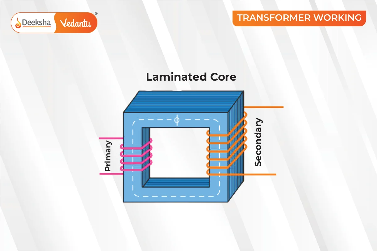
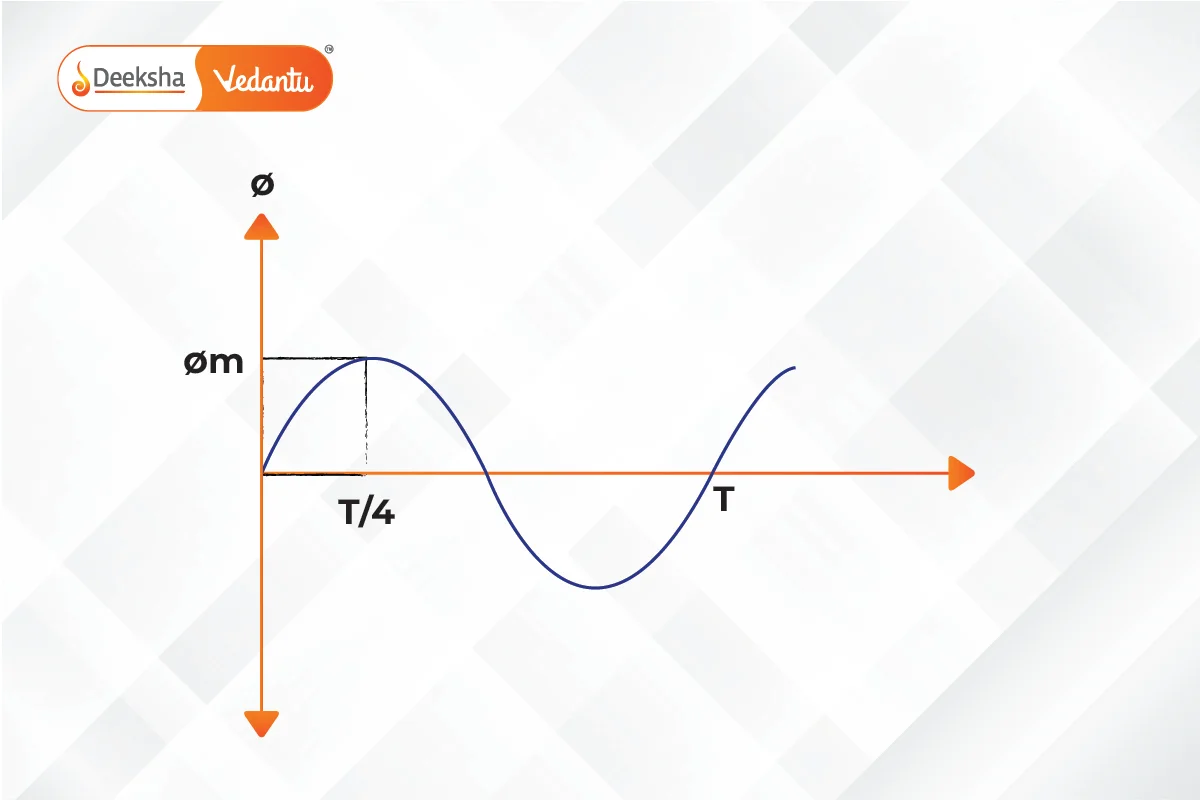
Transformers operate on Faraday’s law of electromagnetic induction and mutual induction. They consist of primary and secondary coils wrapped around a core. When AC passes through the primary coil, it generates a changing magnetic flux, which induces an electromotive force (EMF) in the secondary coil. This process is known as mutual induction.
Parts of a Single-phase Transformer
- Core: Supports the winding and provides a path for magnetic flux.
- Windings: Copper wires wound on the core.
- Primary Winding: Connected to the input current.
- Secondary Winding: Delivers the output voltage.
- Insulation Agents: Prevents short circuits and facilitates mutual induction.
EMF Equation of Transformer

The EMF equation for a transformer is given by:
E1 = 4.44 fΦ m N1
E2 = 4.44 fΦ m N2
Where:
- N1 and N2 are the number of turns in the primary and secondary coils, respectively.
- Φ m is the maximum flux in webers.
- f is the frequency in hertz.
Voltage Transformation Ratio
The voltage transformation ratio
K is defined as:
K= N2 / N1 = E2 / E1
- Step-up Transformer: K>1
- Step-down Transformer: K<1
Transformer Efficiency
Efficiency is calculated by comparing the output to the input power. A high-efficiency transformer has minimal power loss.
η = (OutputPower / InputPower) ×100
Applications of Transformers
- Long-distance electrical energy transmission.
- Voltage regulation in electronic devices like radios and TVs.
- Various voltage requirements in devices with multiple secondary windings.
FAQs
Mutual induction in transformers refers to the process where a change in current in the primary coil induces an electromotive force (EMF) in the secondary coil through a shared magnetic field.
The main types of transformers are step-up transformers, step-down transformers, air core transformers, iron core transformers, autotransformers, power transformers, distribution transformers, measurement transformers, and protection transformers.
Transformers are used in power transmission, voltage regulation, and devices that require multiple voltage levels.
The main components are the core, windings (primary and secondary), and insulation agents.
Transformers operate on the principles of electromagnetic induction and mutual induction.
A step-up transformer increases the output voltage and decreases the output current, while a step-down transformer decreases the output voltage and increases the output current.
The primary purpose of a transformer is to change the voltage level in an AC circuit, either stepping it up or stepping it down.
Related Topics
- Simple Harmonic Motion (SHM)
- Rank of a Matrix and Some Special Matrices
- JEE Main Syllabus 2025
- Semiconductors
- Atomic Structure
- Normality
- Young’s Double Slit Experiment
- Raoult’s Law
- JEE Main Marks vs Rank 2024
- Coulomb’s Law
- Electromagnetic Spectrum
- Correlation Coefficient
- JEE Advanced Marks vs Ranks 2024
- Heisenberg Uncertainty Principle
- Binomial Theorem


Get Social