Introduction to Circuit Diagrams
A circuit diagram is a graphical representation of an electrical circuit, showing how various electrical components are connected together using standardized symbols. It serves as a simplified blueprint for understanding how current flows, how components interact, and how an entire electrical system is designed.
In practice, circuit diagrams are essential tools used by electricians, engineers, and students to analyze, design, construct, and troubleshoot electrical systems. Circuit diagrams make it easier to visualize the layout of a circuit without physically assembling the components. They are also used to communicate electrical designs across various industries and fields.
Symbols Used in Circuit Diagrams
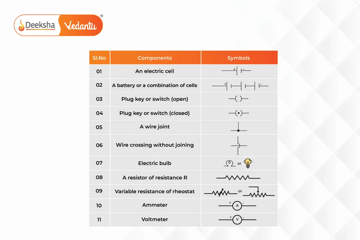
The representation of components in circuit diagrams uses standard symbols. These symbols ensure that circuits are universally understood, regardless of who draws them or where they are used. Below are the symbols for common components:

| Component | Description |
| Battery | A battery is represented by a series of alternating long and short lines. The longer line represents the positive terminal, and the shorter line represents the negative terminal. |
| Cell | A single cell is represented similarly to a battery but with just one pair of a long and short line. It provides voltage to the circuit. |
| Resistor | A resistor is represented by a zigzag line. It is used to limit the current flow in the circuit. |
| Variable Resistor | A variable resistor is represented by a zigzag line with an arrow passing through it, indicating that the resistance can be adjusted. |
| Switch | A switch is represented by a break in the line with a dot on either side, connected by a short angled line. When the line connects the two dots, the switch is closed, allowing current to flow. When the line is angled away, the switch is open. |
| Lamp/Bulb | A bulb is represented by a circle with a cross inside it. It indicates a device that converts electrical energy into light energy. |
| Ammeter | An ammeter is represented by a circle with the letter “A” inside it. It measures the current in a circuit and is always connected in series. |
| Voltmeter | A voltmeter is represented by a circle with the letter “V” inside it. It measures the potential difference and is connected in parallel. |
| Fuse | A fuse is represented by a line with a rectangle or a squiggly line in the middle. It protects the circuit by melting when excessive current flows through it. |
| Ground/Earth | Ground is represented by a series of descending lines of decreasing length (resembling a triangle). It acts as a reference point for the circuit. |
| Diode | A diode is represented by a triangle pointing toward a line (arrow symbol). It allows current to flow in one direction only. |
| LED (Light Emitting Diode) | The symbol for an LED is similar to a diode but includes two arrows pointing away from it, indicating that the diode emits light. |
These symbols are used universally and simplify communication between engineers and electricians.
Different Types of Circuits and Their Diagrams
Series Circuit
A series circuit is one in which all components are connected end-to-end in a single path, meaning the same current flows through each component. If any part of the series circuit is broken, the entire circuit is interrupted.
Characteristics:
- The same current flows through all components.
- The total resistance in the circuit is the sum of the individual resistances:
- The potential difference is shared among all components based on their resistances.
- If one component fails (e.g., a light bulb burns out), the entire circuit stops functioning.
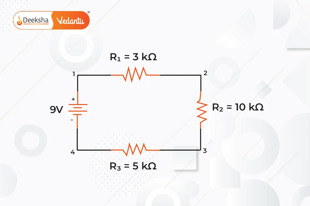
Example of a Series Circuit Diagram:
Let’s draw a simple series circuit consisting of a battery and three resistors:

In this diagram:
- The battery provides the voltage source.
- R1, R2 and R3 are resistors that limit the current.
- The current is the same throughout the circuit.
Parallel Circuit
In a parallel circuit, components are connected across the same two points, creating multiple paths for the current to flow. Each component in a parallel circuit has the same voltage across it, but the current divides among the branches.
Characteristics:
- The potential difference (voltage) across each branch is the same.
- The total current is the sum of the currents through each parallel branch.
- The total resistance is less than the resistance of the smallest individual resistor:
- If one branch fails, the rest of the circuit continues to function.
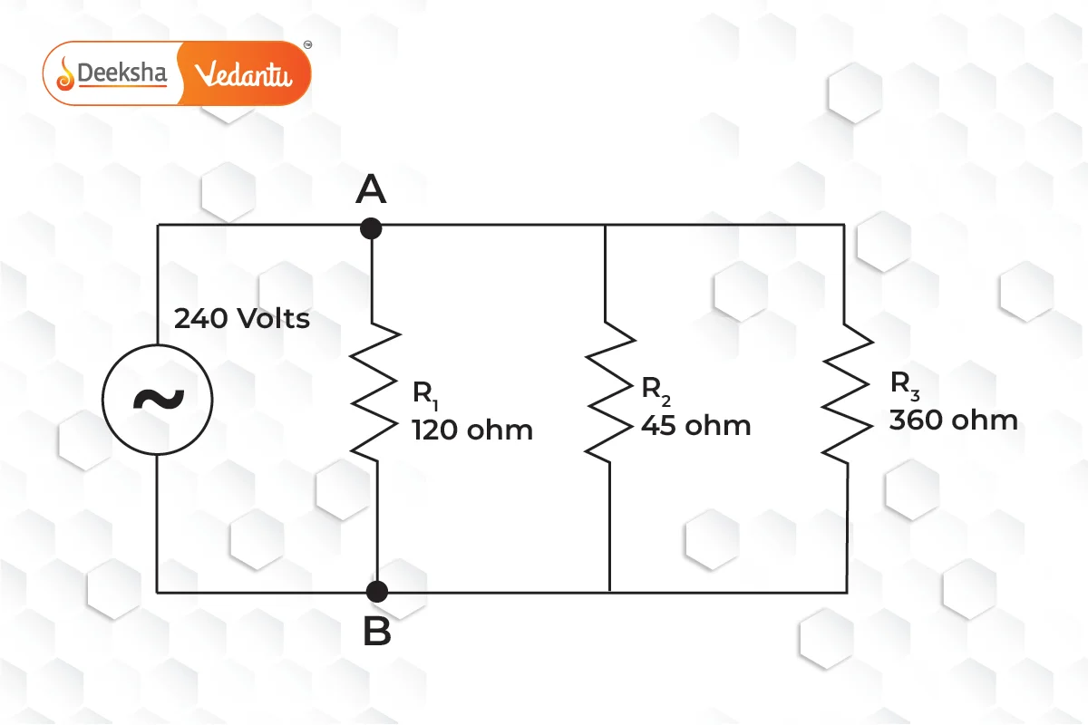
Example of a Parallel Circuit Diagram:
Here’s a simple parallel circuit with a battery and three resistors connected in parallel:

In this configuration:
- The battery provides the voltage across both resistors.
- The current divides between the resistors, but the voltage across each resistor is the same.
- The total resistance is less than either R1,R2 or R3, reducing the overall opposition to current flow.
Combination Circuit (Series-Parallel)
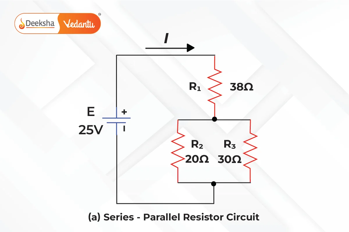
A combination circuit involves both series and parallel connections of components. It is more complex but allows greater flexibility in circuit design. These circuits are common in real-life applications, such as household wiring, where different parts of the circuit may require different arrangements.

In this example:
- R1 is in series with the combination of R2 and R3, which are in parallel with each other.
- The total resistance will involve calculating the parallel resistance first, then adding it to the series resistor.
How to Read and Construct Circuit Diagrams
To successfully read and construct a circuit diagram, follow these steps:
Step-by-Step Guide to Reading Circuit Diagrams:
- Identify the Symbols: Understand what each symbol in the circuit represents, such as batteries, resistors, switches, and other components.
- Follow the Connections: Trace the path of current flow from the power source through the various components. Identify whether the components are connected in series or parallel.
- Determine the Function of the Components: Identify the role each component plays in the circuit (e.g., limiting current, providing power, or switching).
- Calculate Values if Needed: If the diagram provides values for voltage, current, and resistance, use Ohm’s law or other relevant formulas to analyze the circuit.
Steps to Construct a Circuit Diagram:
- Identify the Components Needed: List all components you’ll need in the circuit, such as batteries, resistors, capacitors, etc.
- Decide on Series or Parallel: Determine how the components should be connected (in series, parallel, or a combination).
- Use Symbols: Draw the symbols for each component and connect them with straight lines representing wires.
- Label the Values: If applicable, label the resistance of each resistor, the voltage of the power supply, and other important values.
- Check the Completeness: Ensure all components are properly connected, and there are no open loops unless a switch is intentionally open.
Real-Life Applications of Circuit Diagrams
- Household Electrical Systems: Circuit diagrams are used to design and analyze the wiring systems in homes. For instance, electrical engineers use them to figure out how to wire lighting circuits, fans, sockets, and appliances.
- Electronic Devices: Complex electronic devices such as computers, smartphones, and televisions rely on intricate circuit designs. Engineers use circuit diagrams to layout the circuits that control the flow of current to different components.
- Automobiles: Modern cars are full of electrical systems for things like headlights, wipers, and infotainment systems. Circuit diagrams are used in designing these systems and troubleshooting electrical faults in vehicles.
- Robotics: Robots are powered by electrical circuits that control motors, sensors, and processors. Engineers use circuit diagrams to design the control systems for robots and ensure that they work correctly.
- Medical Devices: Many medical devices, such as heart monitors, X-ray machines, and ventilators, rely on complex electrical circuits. Circuit diagrams help biomedical engineers design and maintain these critical systems.
FAQs
If a component in a series circuit fails (e.g., if a bulb burns out), the entire circuit is interrupted, and current stops flowing through all components.
An ammeter is connected in series with the circuit components to measure the current flowing through the circuit.
A voltmeter is connected in parallel with the component or section of the circuit across which the potential difference (voltage) is to be measured.
Circuit diagrams simplify the understanding of electrical circuits by using symbols to represent components and connections. They help in the design, analysis, and troubleshooting of circuits and are universally understood.
In a series circuit, all components are connected in a single path, so the same current flows through each component. In a parallel circuit, components are connected across the same two points, providing multiple paths for current to flow.
Related Topics
- Bernoullis Principle
- What is Hypothesis?
- Ohm’s Law
- Protection Against Earthquake
- Magnetic Field Due To A Current – Carrying Conductor
- Electricity
- Refraction Of Light
- Dispersion Of White Light By A Glass Prism
- Heating Effect Of Electric Current
- Spherical Mirrors
- The Human Eye And The Colourful World
- Acceleration
- Factors On Which The Resistance Of A Conductor Depends
- Magnetic Effects Of Electric Current
- Full Wave Rectifier


Get Social