Ohm’s Law is about how electric current and voltage are related. It says that the more voltage you put across a conductor, the more current flows through it. A scientist named Georg Simon Ohm from Germany was the first to prove this through experiments.
Ohm’s Law is super important for electric circuits. It says that when you have a conductor, like a wire, the voltage across it is directly linked to the current going through it, as long as everything else stays the same. Mathematically, it’s written as V=IR, where V is voltage, I is current, and R is resistance. Resistance is measured in ohms (Ω). You can also use this formula to figure out current and resistance separately: I=V/R and R=V/I.
But, remember, Ohm’s Law only works if everything else, like temperature, stays constant. If something heats up, like the filament in a light bulb when you crank up the current, Ohm’s Law doesn’t apply. So, while it’s a useful rule, it’s not always absolute.
Statement of Ohm's Law
Ohm's Law is mathematically expressed as:
Where:
= Voltage (or potential difference) across the conductor, measured in volts (V)
= Current flowing through the conductor, measured in amperes (A)
= Resistance of the conductor, measured in ohms (Ω)
This equation implies that:
- Voltage (V) is directly proportional to Current (I) when the Resistance (R) is constant.
- If the voltage increases, the current increases proportionally, assuming the resistance remains constant.
Rearranged Formulas:
We can rearrange the formula to solve for current or resistance:
- To find current (I):
- To find resistance (R):
Understanding Ohm's Law Through Examples
Example 1:
If a resistor has a resistance of 10 Ω, and a voltage of 20 V is applied across it, calculate the current flowing through the resistor.
Solution:
- Given:
,
- Using
- Answer: The current flowing through the resistor is
Example 2:
A circuit has a current of 5 A flowing through it, and the resistance of the conductor is 2Ω. Find the voltage across the conductor.
Solution:
- Given:
,
- Using Ohm's Law:
Answer: The voltage across the conductor is \boldsymbol.
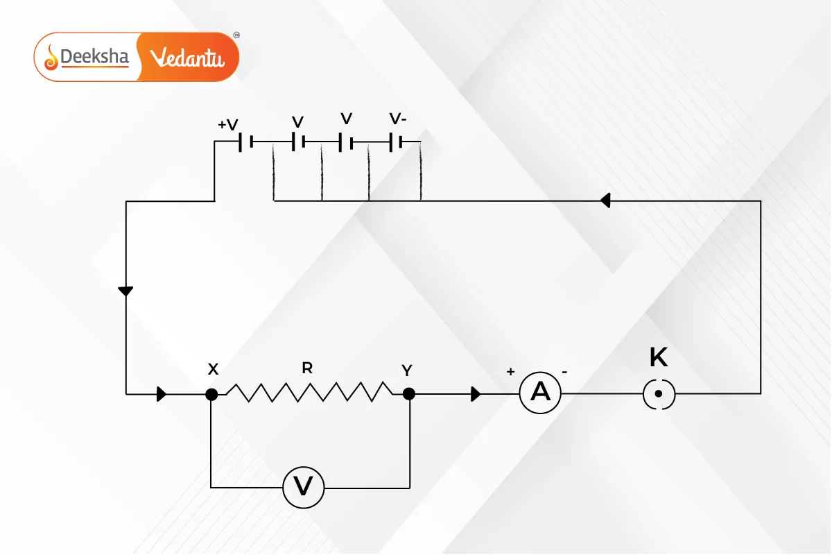
Relationship Between Voltage, Current, and Resistance
Direct Proportionality Between Voltage and Current:
- According to Ohm's Law, if the resistance remains constant, the voltage across a conductor is directly proportional to the current flowing through it.
- If voltage increases, the current increases proportionally, and if voltage decreases, the current decreases as well.
Inverse Proportionality Between Current and Resistance:
- For a constant voltage, current is inversely proportional to the resistance.
- If resistance increases, the current decreases because it is harder for the charges to move through the conductor.
- If resistance decreases, the current increases, as it is easier for charges to flow through the conductor.
Example:
- In a circuit with a constant voltage of 12 V, if the resistance is increased from 2Ω to 4, the current will decrease.
- For
,
- For
,
- For
- Conclusion: When the resistance is doubled, the current is halved.
The Concept of Resistance
Resistance (R) is the opposition that a material offers to the flow of electric current. Different materials offer different levels of resistance based on their properties, such as:
- Length: Longer conductors have more resistance.
- Thickness: Thinner conductors have more resistance.
- Material: Conductors (like copper and aluminum) have low resistance, while insulators (like rubber or wood) have very high resistance.
The SI unit of resistance is the ohm (Ω), and it is defined as:
- A conductor has a resistance of 1 Ω if a current of 1 A flows through it when a voltage of 1 V is applied across its ends.
Ohmic and Non-Ohmic Conductors
Ohmic Conductors:
- Ohmic conductors are materials that obey Ohm's Law. For these materials, the current through the conductor is directly proportional to the applied voltage, provided the temperature remains constant.
- Example: Metals such as copper and aluminum are typical ohmic conductors.
Non-Ohmic Conductors:
- Non-ohmic conductors do not follow Ohm's Law. In these materials, the relationship between current and voltage is not linear. The resistance can change as the voltage or current changes.
- Examples: Diodes, transistors, and filament bulbs are examples of non-ohmic conductors, where the resistance increases as the temperature of the component increases.
Graphical Representation of Ohm's Law
Ohm's Law can also be represented graphically by plotting voltage (V) on the y-axis and current (I) on the x-axis. For an ohmic conductor:
- The graph is a straight line passing through the origin.
- The slope of the line represents the resistance (R) of the conductor.
Characteristics of the Ohm's Law Graph:
- Slope =
, which is equal to the resistance (R).
- A steeper slope indicates a higher resistance, while a flatter slope indicates a lower resistance.
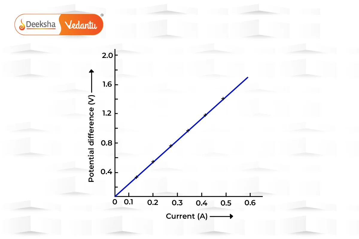
For non-ohmic conductors, the graph is not a straight line and may curve, indicating that the resistance is changing with the current or voltage.
Applications of Ohm's Law
Ohm's Law is widely used in the analysis of electric circuits and plays a crucial role in many everyday devices. Below are some real-world applications:
- Electrical Appliances: Electrical appliances like heaters, ovens, and fans use Ohm's Law to regulate the current flowing through them. By adjusting the resistance, manufacturers can control the amount of current drawn by the appliance, ensuring that it operates safely.
- Circuit Design: Ohm's Law is essential in designing electronic circuits. Engineers use it to calculate the correct values of resistors, ensuring that components receive the right amount of current and voltage.
- Electrical Safety: Ohm's Law helps in designing fuses and circuit breakers. These safety devices are designed to "break" the circuit when the current exceeds a safe limit, protecting appliances and preventing fire hazards.
- Troubleshooting Electrical Circuits: Electricians and technicians use Ohm's Law to troubleshoot faulty circuits. By measuring the voltage, current, and resistance, they can identify components that are malfunctioning or causing excessive resistance in a circuit.
Power Calculation:
- Ohm's Law is used in conjunction with the power formula:
Or, combining it with Ohm's Law:
This allows us to calculate the power consumed by resistive components like electric heaters and lamps.
Key Practice Questions
Q1: A circuit consists of a 9 V battery and a resistor with a resistance of 3 Ω. Calculate the current flowing through the circuit.
- Answer:
Q2: A light bulb has a resistance of 240 Ω, and a current of 0.5 A flows through it. Find the voltage across the bulb.
- Answer:
Q3: If the current in a circuit is 4 A and the voltage is 12 V, calculate the resistance.
- Answer:
Q4: A heater uses a power supply of 220 V, and a current of 10 A flows through it. What is the resistance of the heater?
Answer:
Water Pipe Analogy for Ohm’s Law
Ohm’s Law is like water flowing through pipes. Imagine you have water flowing through pipes, and you can’t see the water molecules, just like we can’t see electrons in electric circuits. When you apply different pressures (similar to voltage in circuits) at each end of the pipes, you get a certain flow of water (like current in circuits) through the pipes. This analogy helps us understand how electric circuits work even though we can’t see the electrons moving.
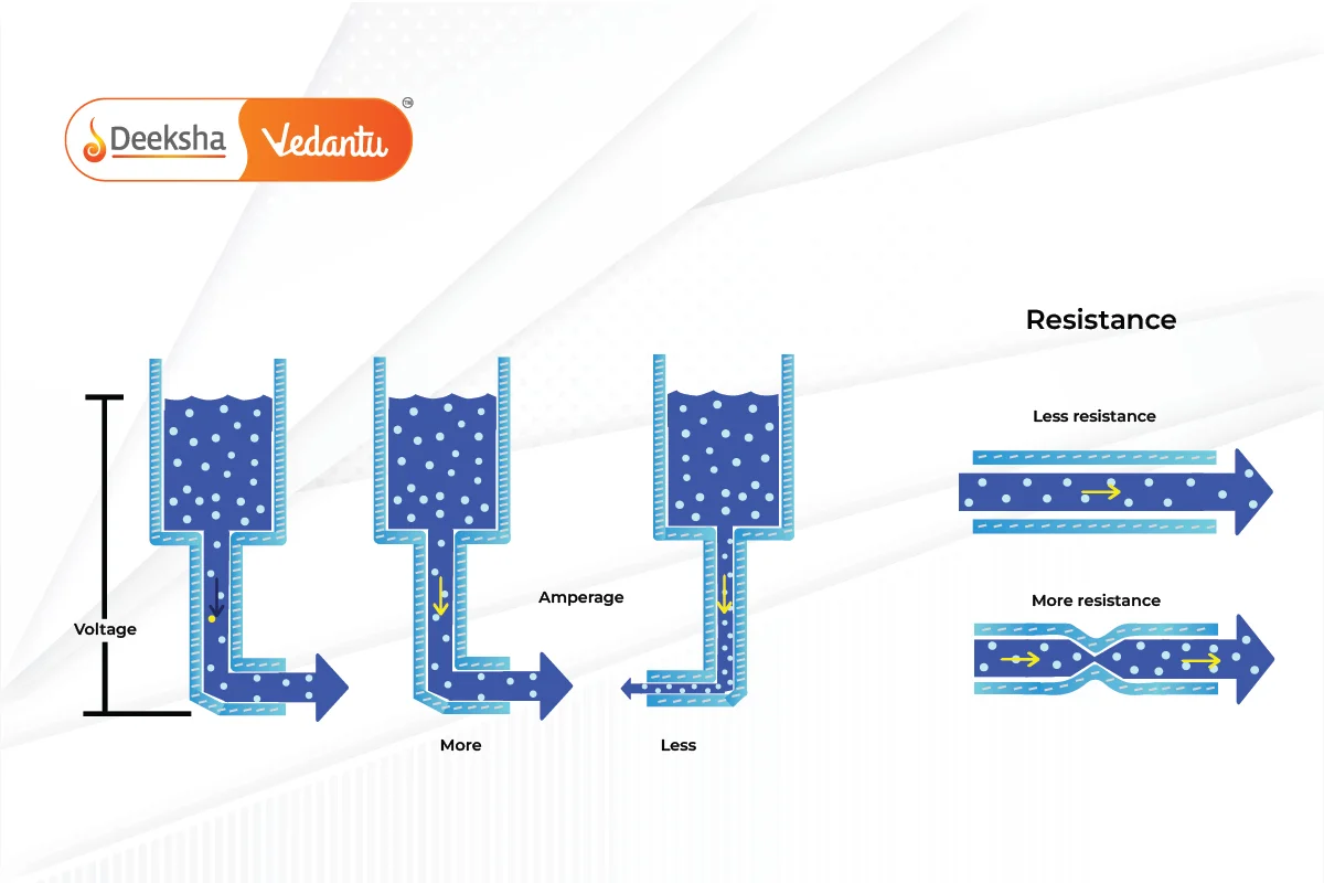
In this analogy, voltage is like the pressure of water, current is the volume of water flowing through the pipe, and resistance is the size of the pipe. So, when you increase the pressure (voltage), more water flows through the pipe (current), especially if the pipe is larger (lower resistance).
Experimental Verification of Ohm’s Law
You can check Ohm’s Law with a simple experiment. Here’s what you need:
- Resistor
- Ammeter (to measure current)
- Voltmeter (to measure voltage)
- Battery
- Plug Key
- Rheostat (a variable resistor)
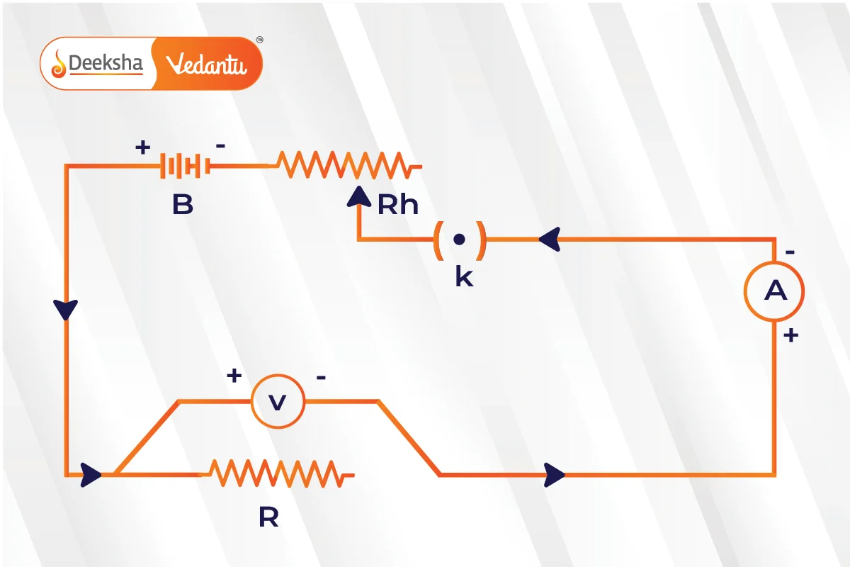
Here’s how to conduct the experiment:
- Start with the key (K) closed and adjust the rheostat to get minimum readings on both the ammeter (A) and voltmeter (V).
- Gradually increase the current in the circuit by adjusting the rheostat. Record the current and corresponding voltage across the resistor (R).
- Repeat step 2 to gather multiple sets of current and voltage values.
- Calculate the ratio of voltage to current (V/I) for each set of values.
- Notice that the ratio V/I is nearly constant for all cases. This constant value represents the resistance (R).
- Plot a graph of current against voltage. It should form a straight line, indicating that current is proportional to voltage.
Ohm’s Law Magic Triangle
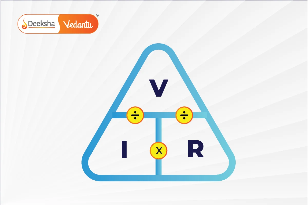
The Ohm’s Law magic triangle is a handy tool for remembering how to calculate voltage (V), current (I), and resistance (R) using different combinations of these variables.
For example, if you need to find voltage and you’re given current (I) and resistance (R), cover up the V at the top of the triangle. You’re left with I and R or I × R. So, to calculate voltage, you multiply current by resistance.
Here’s an example of how to use the magic triangle:
If current (I) = 2 amps and resistance (R) = 5 ohms, you want to find voltage (V).
Using the magic triangle:
- Cover up V at the top.
- You’re left with I and R or I × R.
- So, V = I × R = 2 amps × 5 ohms = 10 volts.
This triangle makes it easier to remember the relationships between voltage, current, and resistance in Ohm’s Law equations.
Calculating Electrical Power Using Ohm’s Law
To calculate electrical power using Ohm’s Law, you can use these formulas:
If you’re given voltage (V) and current (I):
P = V I
If you’re given voltage (V) and resistance (R):
P = V^2 / R
If you’re given current (I) and resistance (R):
P = I^2 R
These formulas help you find power (P) in watts when you know the values of voltage, current, and resistance.
Power Triangle
The power triangle is a useful tool for finding electric power, voltage, and current when you know the values of the other two parameters. Here’s how to use it:
When you’re given current (I) and voltage (V):
Use the formula
P = V I to find power (P).
When you’re given power (P) and voltage (V):
Use the formula
I = P / V to find current (I).
When you’re given power (P) and current (I):
Use the formula
V = P / I to find voltage (V).
These formulas help you determine electric power, voltage, and current using the power triangle.

Ohm’s Law Matrix Table
Creating a matrix table for Ohm’s Law equations is a convenient way to organize the various formulas for quick reference. Here’s how you could structure the table:
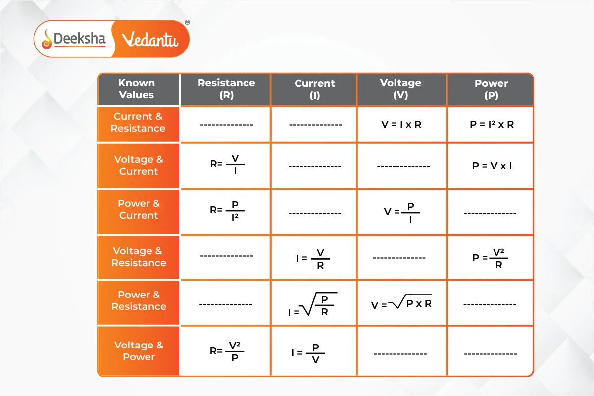
This matrix table provides a clear and concise reference for applying Ohm’s Law in different scenarios.
Ohm’s Law Pie Chart
Creating a pie chart to illustrate Ohm’s Law relationships is a great idea for visualizing the connections between different parameters. Each section of the pie chart represents one aspect of Ohm’s Law, helping learners grasp the relationships more easily.
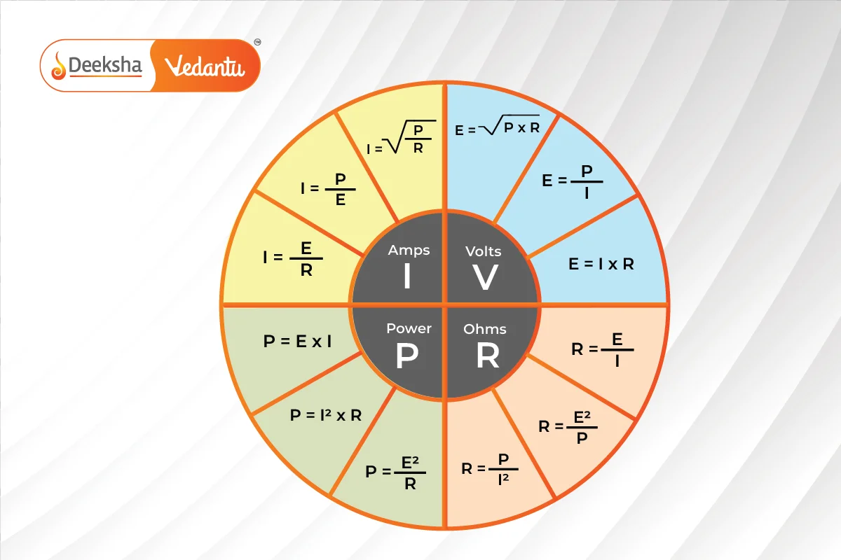
This visual representation can serve as a quick reference for understanding and applying Ohm’s Law in various electrical situations.
Applications of Ohm’s Law
- Determining Circuit Parameters: It’s commonly used to find voltage, resistance, or current in electric circuits.
- Maintaining Voltage Drop: Ohm’s Law helps in ensuring the desired voltage across electronic components, aiding in their proper functioning.
- Instruments Design: It’s utilized in the design of instruments like DC ammeters and shunts to regulate and divert current effectively.
Ohm’s Law limitations
- Not Applicable to Unilateral Elements: It doesn’t apply to unilateral components like diodes and transistors, which only allow current flow in one direction.
- Challenges with Non-linear Elements: For non-linear components with varying parameters like capacitance and resistance, the voltage-current ratio isn’t constant over time, making Ohm’s Law impractical for use.
Understanding both the applications and limitations of Ohm’s Law is crucial for effectively designing and analyzing electrical systems.
FAQs
Ohm’s Law describes the relationship between voltage (V), current (I), and resistance (R) in an electrical circuit. It states that the current flowing through a conductor between two points is directly proportional to the voltage across the two points and inversely proportional to the resistance.
Voltage is measured in volts (V), current in amperes (A), and resistance in ohms (Ω).
Ohm’s Law can be remembered using various mnemonic devices, such as the acronym VIR (Voltage equals Current times Resistance) or the “magic triangle” visualization, where you cover up the variable you want to find and see what’s left in the equation.
Ohm’s Law is used in various applications, including designing electrical circuits, troubleshooting faults, calculating power dissipation, and selecting appropriate resistors for specific voltage and current requirements.
Ohm’s Law is applicable to most passive electrical components like resistors, conductors, and simple circuits. However, it may not apply to complex components like diodes and transistors, which exhibit non-linear behavior.
Ohm’s Law may not be suitable for components with non-linear characteristics or unilateral elements like diodes. Additionally, it assumes constant resistance, which may not hold true in certain situations.
Ohm’s Law can be applied to AC circuits, but because AC circuits involve time-varying voltages and currents, the calculations may become more complex, especially when dealing with reactive components like capacitors and inductors.


![Rendered by QuickLaTeX.com \[\displaystyle\boldsymbol\]](https://deekshalearning.com/wp-content/ql-cache/quicklatex.com-0a2c606b4b8da976bb4f7d0a085fc371_l3.png)


Get Social