Introduction to Electric Current
Electricity powers most of our everyday activities, from switching on a light to operating complex machinery. At the core of electricity is the concept of electric current—the flow of electric charge through a conductor. Electric current is the foundation of electrical circuits and forms the basis for understanding more advanced topics like electromagnetism and electronics.
Electric Current: The Flow of Charge
Electric current is defined as the rate at which electric charge flows through a conductor. When a potential difference (voltage) is applied across the ends of a conductor, free electrons in the conductor are pushed to move, resulting in a flow of electric charge.
- In metallic conductors like copper or aluminum, this flow of charge is carried by free electrons.
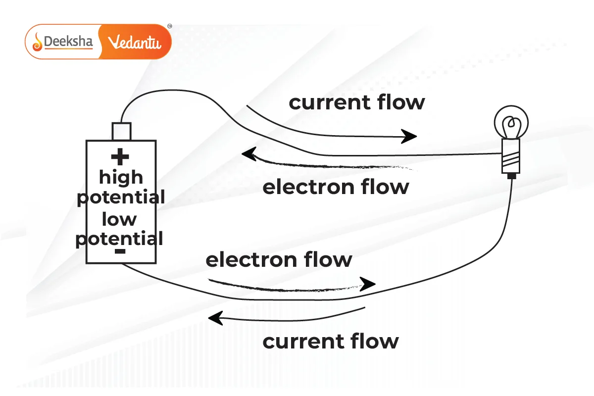
- Electric current flows from regions of higher potential to lower potential in a closed circuit.
The Formula for Electric Current
Mathematically, electric current () is given by the formula:
Where:
= electric current (in amperes,
)
= charge (in coulombs,
)
= time (in seconds,
)
- 1 Ampere of current is defined as the flow of 1 coulomb of charge through a conductor in 1 second.
This formula provides a direct relationship between the amount of charge () flowing through a circuit and the time (
) over which the flow occurs. A large amount of charge passing in a short time results in a high current.
Example:
If a charge of 5 C flows through a conductor in 10 seconds, calculate the current.
- Solution:
- Given:
,
- Using the formula:
- Therefore, the current
Electric Charge: The Basics
Electric charge is a property of subatomic particles, like electrons and protons. There are two types of charges: positive (carried by protons) and negative (carried by electrons). Charges of the same type repel each other, while opposite charges attract.
- The SI unit of charge is the coulomb (C).
- One coulomb of charge is equivalent to the charge carried by approximately
electrons.
The movement of these charges, typically electrons in conductors, results in electric current. Electrons are negatively charged and move from the negative terminal of a battery to the positive terminal when connected in a circuit.
Types of Electric Current
Direct Current (DC)
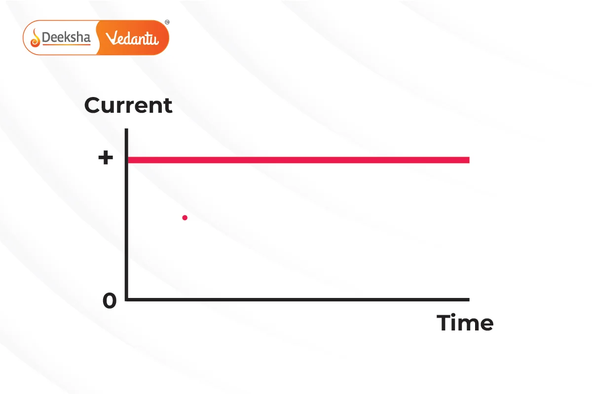
In direct current (DC), the flow of electric charge is unidirectional, meaning the current flows in a single direction. Batteries and cells produce direct current.
- Examples of DC devices: Flashlights, mobile phones, and electric vehicles.
Alternating Current (AC)
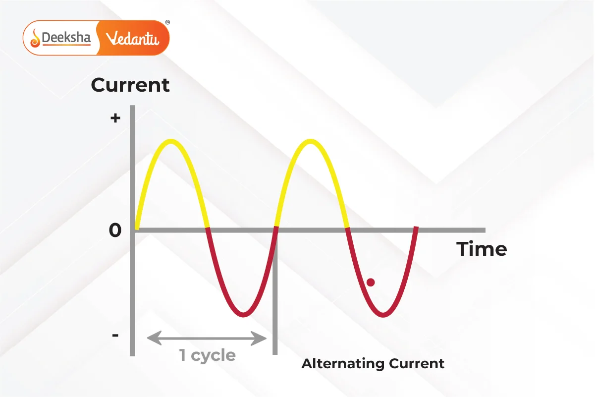
In alternating current (AC), the flow of electric charge periodically reverses direction. The electric power supplied to homes and industries is typically AC, as it can be easily transformed to different voltages.
- Examples of AC devices: Household appliances like refrigerators, washing machines, and air conditioners.
Key Differences Between AC and DC:
- Direction of Flow: DC flows in one direction, while AC changes direction periodically.
- Sources: Batteries and solar cells produce DC; power stations supply AC.
- Applications: DC is used in low-voltage applications, while AC is used for high-power transmission over long distances.
Electric Circuit: The Pathway for Current
An electric circuit is a complete path that allows the flow of electric current from a power source, through electrical components, and back to the source. A basic electric circuit consists of several essential components:
Components of an Electric Circuit:
- Power Source: Provides the potential difference (voltage) that drives the current. Common examples include batteries or cells.
- Conducting Wires: These form the pathway for current to flow. Copper wires are commonly used because of their low resistance.
- Load: A component or device in the circuit that consumes electrical energy and converts it into other forms, such as light or heat. For example, light bulbs, motors, or resistors.
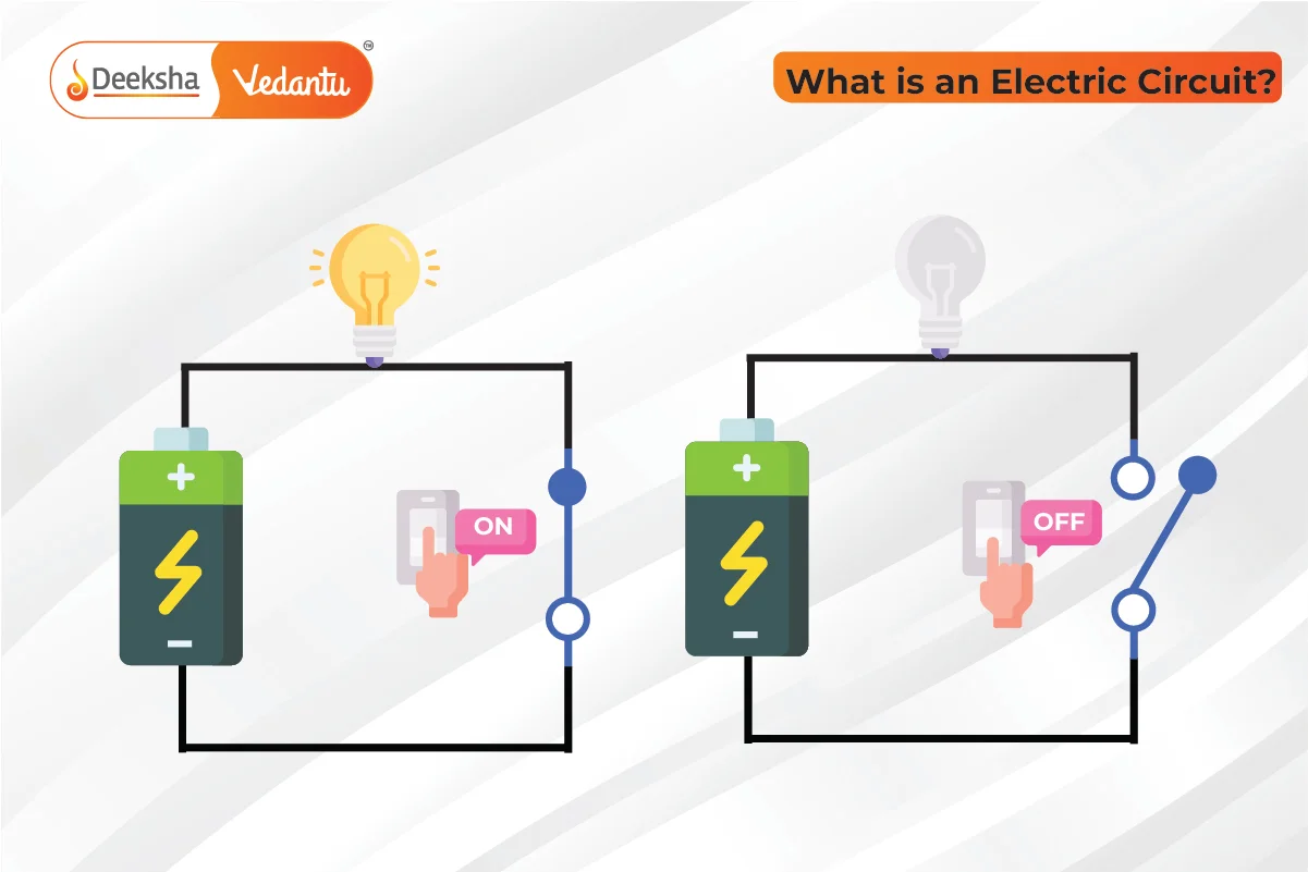
- Switch: Controls the flow of current in the circuit by opening (breaking) or closing (completing) the circuit.
- Ammeter and Voltmeter: An ammeter is used to measure the current flowing through the circuit and is connected in series. A voltmeter measures the potential difference across two points in a circuit and is connected in parallel.
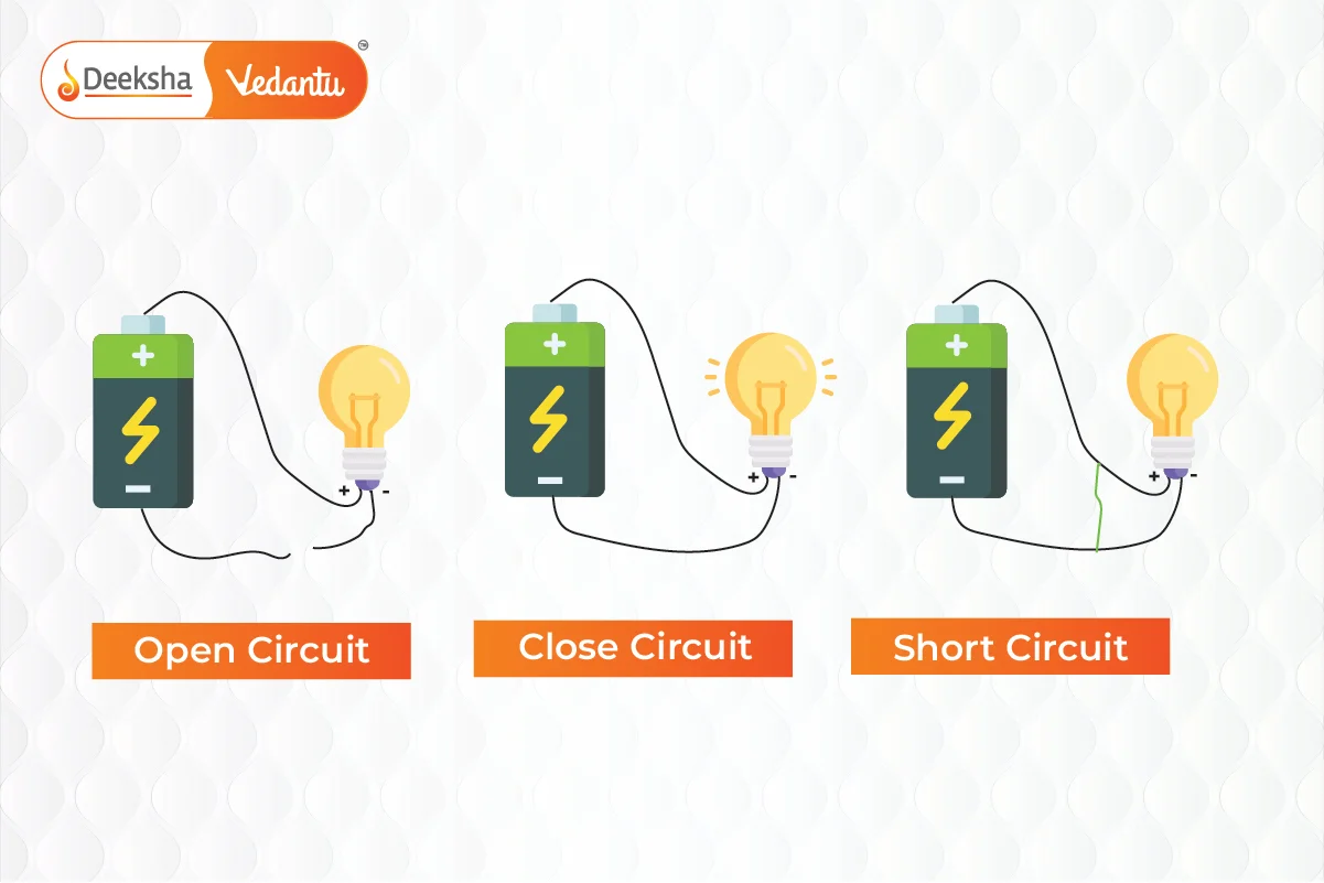
Types of Circuits:
- Closed Circuit: A circuit where the path for current is complete, allowing current to flow and power the devices.
- Open Circuit: A circuit where the path is broken, stopping the flow of current.
- Short Circuit: When current bypasses the normal path, taking an unintended, shorter route. This often results in excessive current, causing overheating or damage to components.
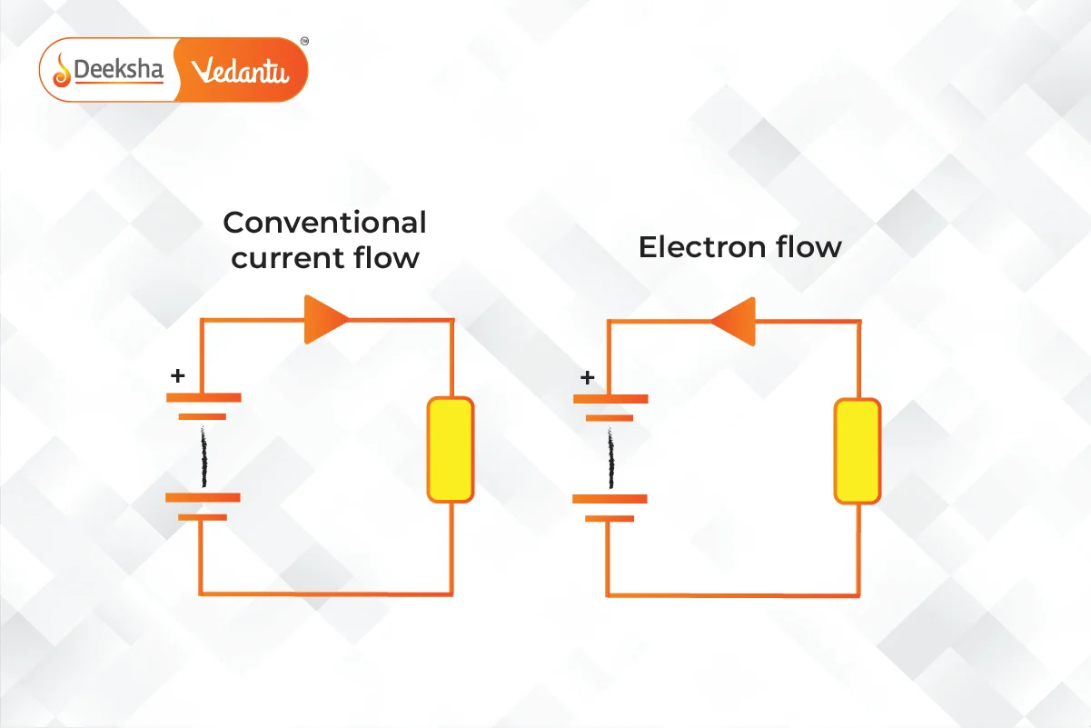
Direction of Current Flow:
- Conventional Current: By convention, electric current flows from the positive terminal to the negative terminal of the power source.
- Electron Flow: In reality, electrons (negatively charged particles) flow from the negative terminal to the positive terminal.
Example:
In a simple electric circuit, a battery of 6 V is connected to a bulb using copper wires. When the circuit is closed (the switch is on), current flows from the battery to the bulb, and the bulb lights up. If the circuit is broken (open circuit), the current stops flowing, and the bulb goes off.
Measuring Electric Current and Potential Difference
Measuring Electric Current
An ammeter is an instrument used to measure the amount of electric current flowing through a circuit. The ammeter is connected in series with the component whose current is to be measured.
- Unit of Current: The unit of electric current is ampere (A). Smaller currents are measured in milliamperes (mA), where 1 A = 1000 mA.
Measuring Potential Difference (Voltage)
Potential difference or voltage between two points in a circuit is the work done to move a unit charge from one point to another. It is the driving force behind the movement of electrons. The instrument used to measure voltage is called a voltmeter, which is connected in parallel with the component across which the voltage is to be measured.
- Unit of Voltage: The unit of potential difference is the volt (V).
Example:
If a 6 V battery is connected to a bulb with a resistance of , calculate the current flowing through the circuit.
- Solution:
- Using Ohm's Law:
- Rearranging:
- The current flowing through the circuit is
.
Real-Life Applications of Electric Current and Circuits
- Household Electrical Wiring: Electrical circuits in homes are designed to provide power to lights, fans, and appliances. Each device is part of a larger circuit that receives power from the main electrical grid.
- Electronic Devices: Devices like smartphones, computers, and televisions rely on well-designed circuits that regulate the flow of current to power components and perform tasks like processing data, displaying images, and making calls.
- Electric Vehicles (EVs): Electric vehicles operate using large electric circuits where current flows from the battery to the electric motors, providing the necessary torque to move the vehicle. The ability to control current flow efficiently is critical in EVs for smooth and controlled driving.
- Medical Devices: Machines such as ECG monitors, pacemakers, and MRI scanners all rely on carefully controlled electric circuits to function correctly and safely.
Key Practice Questions
Q1: A circuit consists of a 12 V battery and a bulb with a resistance of 6 Ω. What is the current flowing through the circuit?
- Answer:
- Using
- Using
Q2: How much charge flows through a circuit in 8 seconds if the current is 0.25 A?
- Answer:
Q3: In a circuit, a current of 5 A flows for 3 minutes. Calculate the total charge that passes through the circuit.
- Answer:
FAQs
A switch controls the flow of current by either completing or breaking the circuit. When the switch is closed, the circuit is complete, and current flows. When the switch is open, the circuit is incomplete, and current stops flowing.
The SI unit of electric current is the ampere (A). It is measured using an ammeter connected in series with the circuit.
Direct current (DC) flows in one direction, while alternating current (AC) changes direction periodically. Batteries produce DC, while power plants generate AC.
Electric current is the flow of electric charge through a conductor. It is defined as the rate at which charge flows through a point in a circuit and is measured in amperes (A).


Get Social