Electric circuits that convert AC (alternating current) to DC (direct current) are known as rectifiers. There are two main types: Half Wave Rectifiers and Full Wave Rectifiers. While half wave rectifiers use only half of the input AC cycle and lose significant power, full wave rectifiers utilize the entire AC cycle, providing a smoother and more consistent DC output. This article delves into the working and characteristics of full wave rectifiers.
What is a Full Wave Rectifier?
A full wave rectifier is a device that converts the entire cycle of alternating current into pulsating direct current. Unlike half wave rectifiers, which use only one half of the AC cycle, full wave rectifiers make use of both halves, thereby improving efficiency and output stability.
Full Wave Rectifier Circuit
Full wave rectifiers can be constructed in two main ways:
- Center Tapped Full Wave Rectifier: Uses a center-tapped transformer and two diodes.
- Bridge Rectifier: Uses a standard transformer and four diodes arranged in a bridge configuration.
This discussion will focus on the center-tapped full wave rectifier.
Center Tapped Full Wave Rectifier Circuit
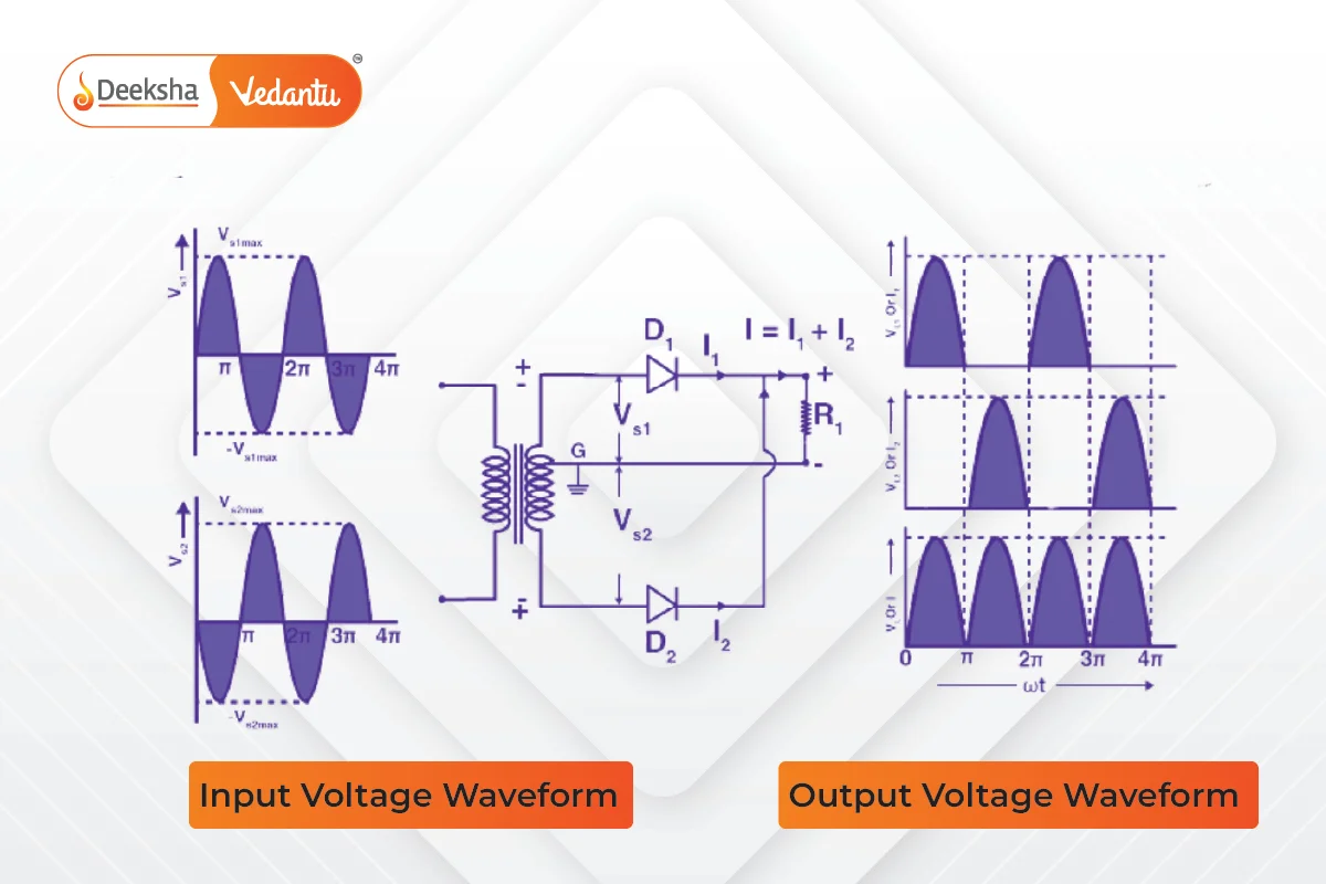
The circuit consists of a step-down transformer and two diodes connected with a center tap. The output voltage is measured across a load resistor connected to the circuit.

Working of Full Wave Rectifier
- Positive Half Cycle:
- During the positive half cycle of the AC input, the top half of the secondary winding becomes positive, and the bottom half becomes negative.
- Diode D1 is forward biased (conducts), and diode D2 is reverse biased (does not conduct).
- The current flows through D1, providing a path to the load resistor.
- Negative Half Cycle:
- During the negative half cycle, the polarity of the secondary winding reverses.
- Diode D1 becomes reverse biased, and diode D2 becomes forward biased (conducts).
- The current flows through D2, continuing to provide a path to the load resistor.
Thus, the circuit rectifies both halves of the AC cycle, producing a continuous pulsating DC output.
Formulas for Full Wave Rectifier
- Peak Inverse Voltage (PIV):
- The PIV across each diode in a full wave rectifier is twice that of a half wave rectifier.
- DC Output Voltage:
- The average DC output voltage is given by:
- RMS Value of Current:
- The RMS value of the current is:
- Form Factor:
- The form factor is calculated as:
- Peak Factor:
- The peak factor is:
- Rectification Efficiency:
- The efficiency of the full wave rectifier is:
Advantages of Full Wave Rectifier
- Higher Efficiency:
- Full wave rectifiers have a rectification efficiency of 81.2%, compared to 40.6% for half wave rectifiers.
- Lower Ripple Factor:
- The ripple factor in full wave rectifiers is 0.482, compared to 1.21 in half wave rectifiers, requiring simpler filters.
- Higher Output Voltage and Power:
- Full wave rectifiers provide higher output voltage and power than half wave rectifiers.
Disadvantages of Full Wave Rectifier
The primary disadvantage is the need for more circuit elements compared to half wave rectifiers, making full wave rectifiers costlier to build.
FAQs
Full wave rectifiers are used in power supplies for electronic devices, battery charging circuits, and any application requiring a steady DC voltage.
Full wave rectifiers have higher efficiency, lower ripple factor, and provide higher output voltage and power compared to half wave rectifiers.
The rectification efficiency of a full wave rectifier is 81.2%, which is higher than the 40.6% efficiency of a half wave rectifier.
A full wave rectifier uses either a center-tapped transformer with two diodes or a bridge configuration with four diodes to rectify both halves of the AC cycle, providing a continuous DC output.
A full wave rectifier converts the entire cycle of alternating current (AC) into pulsating direct current (DC), utilizing both halves of the AC cycle.


Get Social